
About the Header
Engineers imaged a pre-amplification circuit board with transparency assigned to the lower-density components, including the board’s base structure. Using CT data analysis, engineers can assess contacts, proper seating and alignment of board components, and the quality of individual hardware components on the board.
Computed tomography or CT imaging is best known for diagnosing medical conditions. Southwest Research Institute is exploring its use in engineering and physical science applications. SwRI recently acquired one of the most powerful industrial CT imaging machines in the state of Texas. This equipment can create three-dimensional volumetric reconstructions of high- and low-density objects, from fabrics and composites to ceramics and metals.
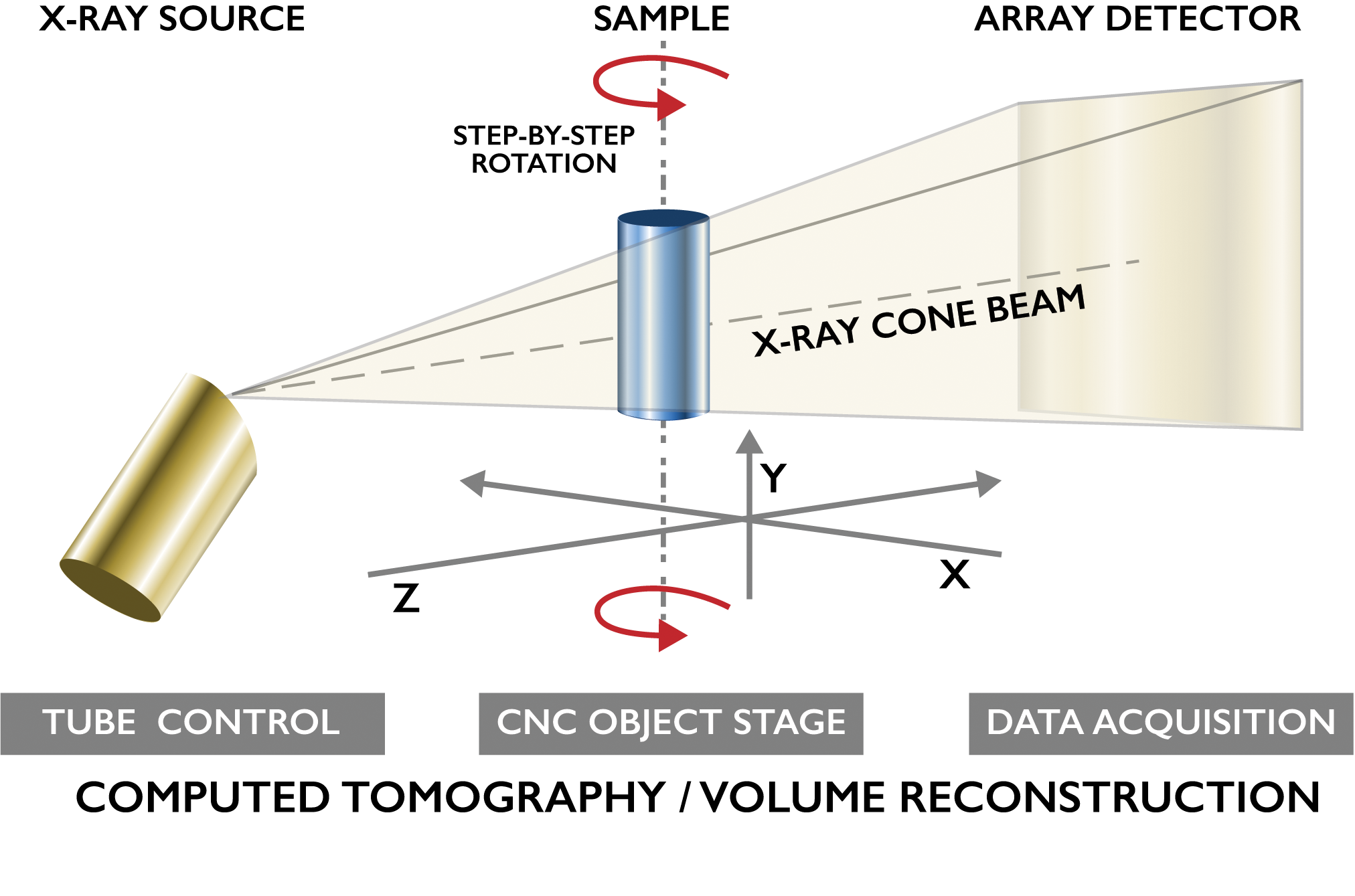
SwRI’s CT machine uses high-power X-rays to create a two-dimensional (2-D) projection of each cross-section image. These 2-D images are combined into a 3-D volumetric image that can reveal minute details of the object, from its surface to its core. During actual data acquisition and analysis, the computer images can be rotated in real time, allowing engineers to see and investigate the hidden anatomy, framework, and texture of complex materials and components.
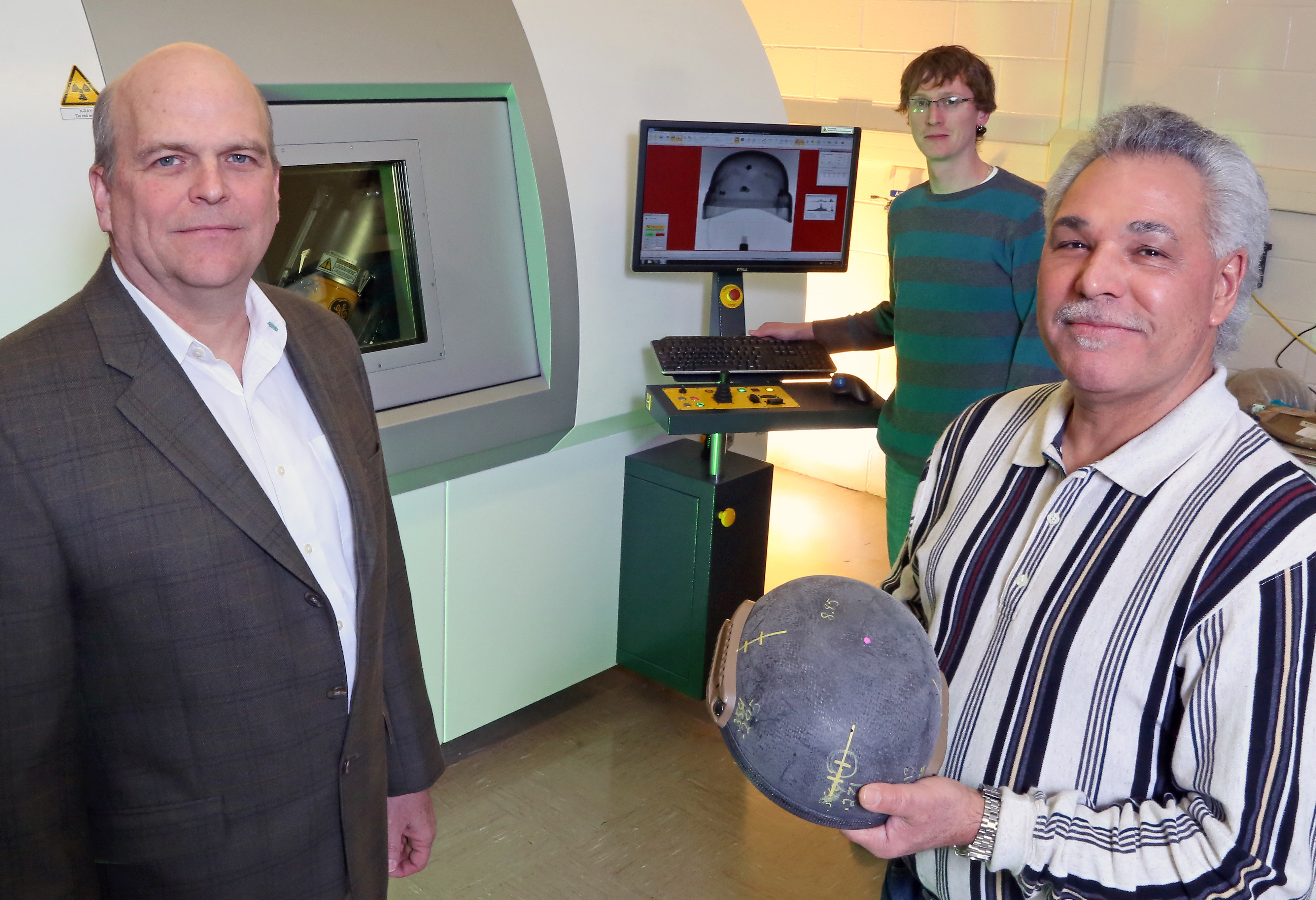
Dr. Christopher Freitas (front right), a program director in the Mechanical Engineering Division, develops computational techniques and experimental methods ranging from fluid flow to terminal ballistics and blast. Dr. Keith Bartels (left) is a staff electrical engineer with more than 30 years of experience in signal and image processing, particularly in medical and nondestructive evaluation applications. Rory Bigger (back right) is a mechanical and aerospace engineer focused on computational mechanics, scientific visualization, and gas dynamics.
Military Applications
Initially, SwRI engineers used CT scanning to diagnose potential problems with military-grade armor and helmets, known as personal protection equipment (PPE). People have been using armor and shields for thousands of years. Protective animal hides and wooden helmets evolved into thin sheets of metal fashioned into increasingly effective, elaborate suits of armor. The development of cannons and guns in the 1500s allowed projectiles to penetrate traditional armor. Increasing metal thickness improved survivability, but eventually metal armor proved too heavy and cumbersome for practical use. In the 1960s, the first lightweight, bullet-resistant materials were developed.
Today’s higher velocity and armor-piercing munitions led to reinforcing PPE with complex, multilayered inserts. These plates — with a ceramic face and compos-ite fabric backing — absorb and dissipate a projectile’s kinetic energy and momentum, reducing the likelihood of fatal injuries. As a projectile strikes the armor’s face, the ceramic and bullet undergo a complex dynamic response. The ceramic plate shatters locally and turns to rubble, which slows, blunts, and potentially fractures the bullet. Then the composite backing spreads the energy of the impact across a larger cross-sectional area and ultimately stops the residual bullet fragments. These complex and layered materials provide effective protection, but are difficult to evaluate for initial manufacturing quality and flaws. They are similarly challenging to evaluate for progressive wear and damage during service.
DETAILS
Computed tomography processes and combines many X-ray images taken from different angles to produce cross-sectional images – virtual slices – of specific areas of a scanned object. CT allows you to peek inside a 3-D object.
The Office of Naval Research and Special Operations Command asked SwRI to assess various nondestructive methods to evaluate the quality of, and damage to, body armor plates and combat helmets. SwRI engineers studied how to assess the quality of enhanced small arms protective insert (ESAPI) plates at delivery and over time, as the equipment was stored and used. Flaws or damage in armor plates can include cracks in the ceramic, flaws in the layer bonding the ceramic with the composite, and voids and delamination in the composite backing material. Combat helmet flaws typically occur in the composite material or the bond layers between the different composite materials used in a specific helmet design — for example, between the carbon outer shell and the polyethylene inner shell. Currently, the military uses 2-D X-ray inspection techniques, which require a technician to manually review images to identify cracks in the ceramic strike face.
DETAIL
The U.S. Armed Forces began using enhanced inserts in 2005 to provide protection from 0.30-06 M2 armor-piercing rounds with a steel or tungsten penetrator. These enhanced plates are more complex and come with 50 percent cost markup
The SwRI team reviewed a broad range of nondestructive evaluation methods, including ultrasound, thermography, eddy current, 2-D X-ray, and interferometry, as well as optical coherence and electrical resistance tomography. CT scanning provided the best balance between ease of use, measurement accuracy, maturity of technology, and usage costs.
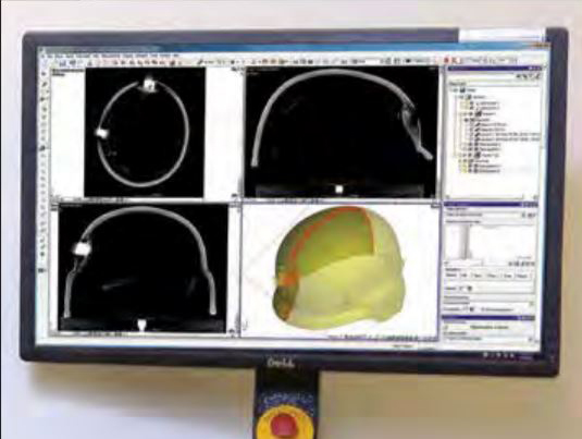
Using CT image data, SwRI engineers developed a suite of software tools to automatically assess the quality of ESAPI plates and combat helmets. After a few simple keystroke inputs, the software system automatically reconstructs the images and analyzes the 3-D volume. The outcome is displayed as a stoplight plot. Green indicates no detected flaws, red highlights detected flaws, and yellow suggests further data review. In this new process workflow, a technician is no longer required to visually inspect each ESAPI plate or combat helmet. The SwRI-developed software suite is called Enhanced SwRI Projection Reconstruction Software or ESPReSo. As part of this software system, supplemental software automatically detects cracks in the ceramic, voids in composites, and delamination at bondline interfaces.
The CT imaging process collects 2-D X-ray projections and reconstructs and visualizes them as a 3-D volumetric data set.
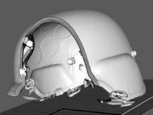
The CT image of the helmet shows where a projectile impacted and was halted by the composite material of the helmet.
The Case for CT Inspection
Once SwRI demonstrated the effectiveness of CT imaging to evaluate armor plates and combat helmets, researchers realized these tools could be used for other personal protection equipment and components.
Based on interest from military clients, SwRI set out to acquire a new, high-powered CT machine.
SwRI’s high-resolution machine has a microfocus, variable-power X-ray tube capable of imaging materials at the micron level. Maximum voltage and power are 240 kilovolts and 320 watts. The 16-inch square surface image plate offers high-definition resolution at speeds of 8 frames per second. The machine accommodates samples up to 20 inches wide, 31 inches high, and 110 pounds. A high-speed, multi-GPU workstation provides quick reconstruction of image data. The dual CPU workstation has 128 GB of RAM, supplemented by a parallel GPU processing subsystem with more than 5,000 processors. Powerful graphics cards and visualization software support tools for metrology as well as porosity and inclusion analyses. The software automatically generates surface and volume data. A free version of the visualization components of the software is available for clients.
Broader Applications
Since October 2015, SwRI has imaged a range of objects beyond the original application of personal protection components. The imaging team has scanned and analyzed a range of components, including automobile cylinder heads, canister filters, medical devices, electronic circuit boards, multiply fabrics, and soil samples. Engineers anticipate using CT image data analysis to diagnose material characteristics and potential maladies for a wide range of applications, supporting almost any project requiring detailed analysis of internal structures.
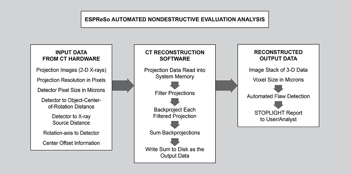
SwRI developed ESPReSo to automatically evaluate armor components for flaws. A stoplight report indicates if armor is sound (green), has flaws (red), or should be evaluated further (yellow).
Questions about this article? Contact Chris Freitas or call +1 210 522 2137 or contact Keith Bartels or call +1 210 522 6062.