Background
Electrified vehicles (full electric and hybrid) present an opportunity to reduce tailpipe emissions in the transportation sector, and as much of the research funding in this sector is transitioning to electrified vehicles, the Institute’s capability to analyze and control electrified powertrains must evolve at the same pace. This evolving capability includes continuing to provide component- and vehicle-level dynamometer testing using established motor-control techniques in combination with innovative tactics for benchmarking stock control strategies and in-vehicle motor performance. For the most precise measurements of efficiency, heat transfer, noise, and vibration, the drive unit (the motor, gear reduction, and differential packaged into a single case, as shown in Figure 1) must be removed from the vehicle and operated on a component dynamometer.
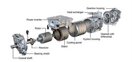
Figure 1: Electric Vehicle Drive Unit.
As the vehicle’s stock inverter (the device controlling the electric motor) is reluctant to operate outside of the vehicle, a programmable or “open” inverter is used to control the drive unit in the test cell. For this type of drive unit testing to be representative of vehicle performance, it is necessary for the stock control strategy to be replicated as closely as possible in the test cell. Division 03’s methodology to replicate stock motor control strategies on the SwRI’s Open Inverter (SOI) has been a key enabler for testing fluids and drive-unit components, supporting projects with Afton, Chevron, Eaton, ExxonMobil, and Cargill, among others. Prior to this project, this approach required time-consuming empirical calibration for motor-performance characterization. Further, this method had the potential for isolated motor performance to be misaligned with in-vehicle performance as only speed and torque outputs of the drive unit can be matched to vehicle operation rather than the electrical control setpoints used in the inverter. The difficulty in identifying stock control strategies is that clear measurement of the motor rotor’s angular position is mandatory for motor control. In production drive units, rotor position is reported by a resolver, which provides absolute position even when the motor is stationary. Generally, direct interpretation of the resolver is not possible in-vehicle as tapping this signal has proven to disrupt vehicle operation. However, Division 03 has recently developed a method to passively monitor the resolver signals and convert those signals to a usable position. The work accomplished here developed and validated the process of measuring inverter control variables and replicating those values on drive unit testing.
Approach
The first portion of the experiment was the initial installation and setup of the passive resolver-to-digital converter (RDC-BOT) and collection of baseline vehicle data on a chassis dyno. This included instrumentation, troubleshooting, and fitment to ensure accurate data. The second portion of the experiment was to analyze the baseline data for rotating-reference-frame values. Following these vehicle tests, a drive unit was installed on a component dyno test cell, upon which the control and test conditions were duplicated. The data was then compared to the baseline vehicle data. Figure 2 shows the generic setup outline with Division 03’s chassis dyno test cell (with the loaded Ford F-150 Lightning vehicle) and Ann Arbor Technical Center (AATC) test cell (component test cell with Tesla Model 3 drive unit). Figure 2. Overview of technical setup components and equipment. In the proposed experiments, the process will be broken down into the following stages:
- Instrument the demonstration vehicle for at least two phases of voltage and current readings, in addition to the three resolver signals.
- Install vehicle onto the chassis dyno with the passive RDC-BOT and power analyzer connected.
- Configure the analysis equipment to calculate rotating reference frame values. Determine the resolver offset in a separate test.
- Operate the vehicle over a steady state test matrix that covers much of the speed/torque envelope of the motor.
- Generate a map of the rotating-reference-frame values and convert those parameters into the preferred format for the programmable inverter.
- Install the demonstration drive unit into a component test cell with a programmable inverter.
- Repeat the cycle setpoints of the vehicle test matrix while controlling to the Id and Iq setpoints recorded on the vehicle.
- Analyze and compare the torque generation of the drive unit in both test cell configurations.
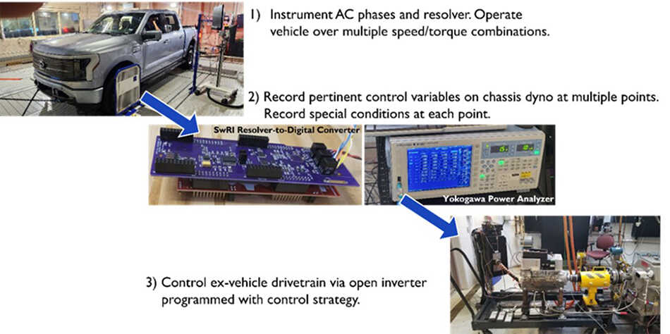
Figure 2. Overview of Technical Setup Components and Equipment.
Accomplishments
SwRI has successfully built, installed, and operated the RDC-BOT. This passive RDC-BOT can operate at various resolver excitation frequencies and voltages with proper signal conditioning to prevent signal corruption of a stock controller when present. The RDC-BOT has been installed and operated in the Chevrolet Bolt, Ford F150 Lightning, and Tesla Model 3 to confirm the ability to monitor position signals without interfering with the vehicle’s performance. The RDC-BOT has successfully operated in conjunction with a power analyzer to output live quadrature- and direct-axis currents on the Tesla Model 3. Comparison between the Tesla Model 3 vehicle data and component drive unit data confirmed performance difference hypothesis previously set forth by the team. The full component hardware and firmware were developed by and belong to SwRI, with client interest in vehicle and vehicle-related benchmarking and power analyzer fields. This benchmarking methodology allows for more accurate understanding of electric vehicle control performance and operation, which can be utilized for troubleshooting and development purposes.