Background
Gas chromatography-mass spectrometry (GC-MS) has long been considered a “gold standard” for quantitative analytical analyses of a variety of small molecules. Making these benchtop systems into field-portable instruments would greatly expand the analytical capability of landed space missions in addition to a variety of Earth science based in situ measurement applications. Recently, SwRI has developed the MAss Spectrometer for Planetary EXploration (MASPEX), a sensitive, high-resolution mass spectrometer as part of NASA’s Flagship Europa Clipper Mission. Using our previous instrument development heritage, the primary objective of this research is the development of a novel ion optical interface between a gas chromatograph and ZigZag time-of-flight mass spectrometer (ZZ-TOF-MS). Successful instrument development would lead to a compact GC-MS system for identification and quantitation of complex sample matrices for future landed missions at Enceladus, Europa and Titan.
Approach
The ion source, ion optical interface region to the time of flight (TOF), and the TOF were designed with SIMION for ray tracing of ion optical paths from ion birth in the ion source region to ion detection in the ZZ-TOF-MS. The SIMION ray tracing is used for maximizing the sensitivity (number of ions) introduced into the TOF extraction region and resolution of the ions separated in the ZZ-TOF-MS. The block diagram of the initial proposed design showing the ion source, transfer ion optics region, and ZZ-TOF-MS is displayed in Figure 1. The ion source (section A in Figure 1) ionizes the neutral gases separated in the gas chromatograph (GC) and then transfers those ions to a second ion optical region which transmits the ions through a quadrupole triplet (section A’ in Figure 1) into the orthogonal acceleration (OA) source of the ZZ-TOF-MS (section C in Figure 1). The gas loads from the helium carrier gas flow rates of the GC separation are used to determine the pumping capacity and aperture or slit size of each differentially pumped region of the GC-MS interface to achieve lower pressures through each successive region and the lowest pressure achieved in the mass analyzer region. The ZZ-TOF-MS is designed with trade space parameters of size (mass), ion transmission (sensitivity), and mass resolution.
The instrument was assembled in a piecemeal fashion with testing occurring first with the ion source followed by incorporation of the transfer ion optics region and the ZZ-TOF-MS. The SwRI Precision Machining Facility, SwRI Main Machine Shop, and Xometry performed the hardware fabrication.
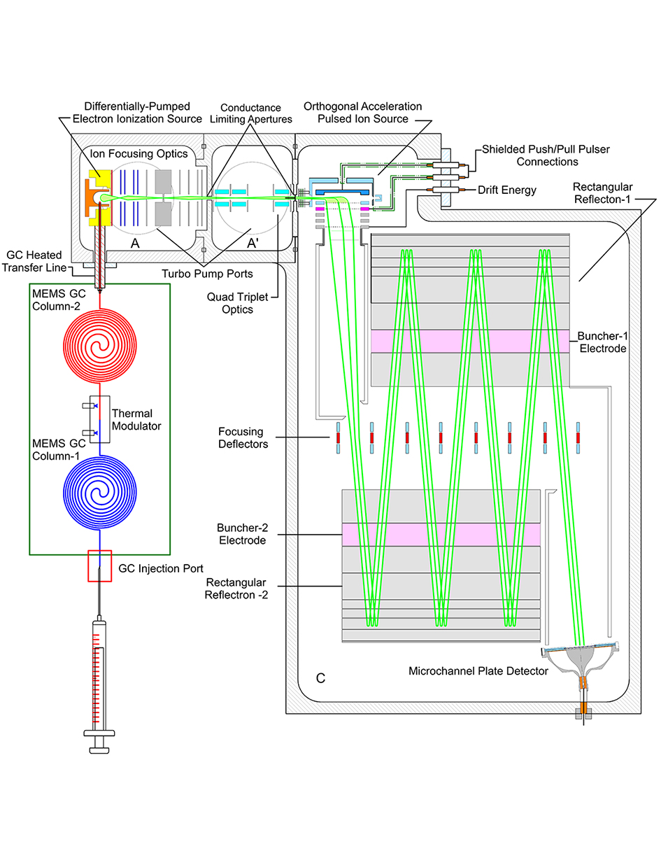
Figure 1: Block diagram of the proposed ion optics coupling the GC to the ZZ-TOF-MS.
Accomplishments
The ion source was built, assembled, and tested. A photograph of the ion source is displayed in Figure 2 (left panel). The ion source ionizes the neutral gases separated in the gas chromatograph (GC) and then transfers those ions to the orthogonal acceleration (OA) source in the ZigZag time-of-flight mass spectrometer. (ZZ-TOF-MS). The low mass carrier gas (hydrogen or helium) ion removal has been proven through experimental testing. This allows for the target analyte ions of higher m/z range (40 u and above) to be enriched and transferred to the orthogonal acceleration source for mass analysis by the ZZ-TOF-MS. Ion beam current measurements have been made at a channeltron electron multiplier behind the beam-defining slit. The beam current measurements as a function of the draw-out half-plate (steering) voltages (labeled as draw-out in Figure 2 left panel) of the ion source are displayed in Figure 2 (right panel). A low voltage applied to the left half plate with the right half plate at -23.7 V (larger electric field) demonstrates transmission of low m/z ions (H2 and He) through the beam-defining slit. At higher voltages applied to the left half plate (lower electric field), approaching the static voltage of -23.7 V on the right half plate, ions of higher m/z are passed through the beam defining slit. (Ne, N2, Ar, and even Xe although the Xe data is not shown). This testing demonstrated successful operation of the ion source and the ability to transmit m/z ≥ 40 u while eliminating unwanted low m/z ions. This mass range is the prime target for organic species to be separated by the GC.
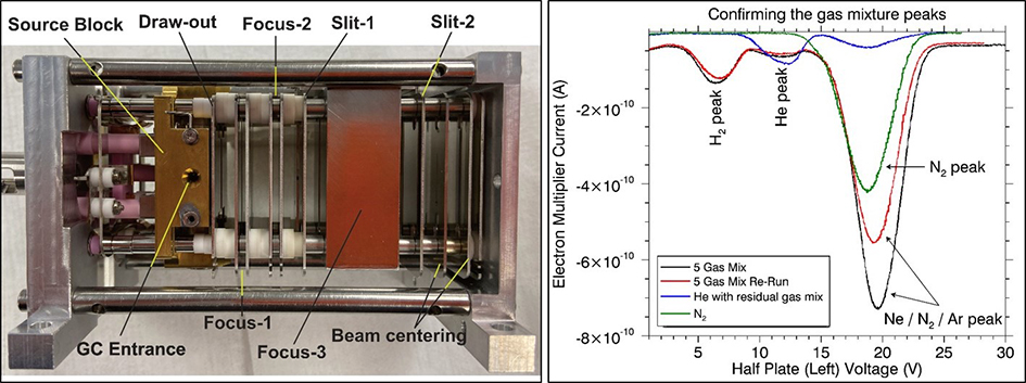
Figure 2: Photograph of the ion source (left panel) with ion optical components labeled. The draw-out plate is a set of half plates that are designated as the right and left half plates to create the electric field for the “steering” of ions out of the ion source. The voltage scanning of the left half plate of the draw-out electrode with right plate voltage fixed is displayed at right for a five-gas mixture (H2, He, Ne, N2, Ar) and pure He and N2 gas for verification of detected gases transmitted through the ion source.
The ion optical components comprising the ZZ-TOF-MS were tested in SIMION, mechanically designed for alignment and fixturing in CAD software to fit inside the custom-made vacuum housing and fabricated by the aforementioned machine shops. A photograph of the completed ion optical assembly of the ZZ-TOF-MS inside the custom-made aluminum vacuum housing is displayed in Figure 3. A photograph of the ion source mounted on top of the aluminum vacuum housing is displayed in Figure 4. A commercial-off-the-shelf vacuum cross is placed around the ion source on the lid (but is omitted for the photograph in Figure 4). The GC outlet is coupled directly to the ion source (Figure 2 left panel) to ionize the eluting components from the GC separation. The instrument assembly is ready for test with a commercial GC or a micro-electro-mechanical system (MEMS) GC.
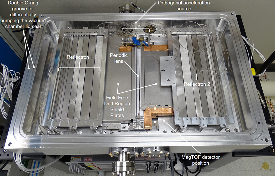
Figure 3: Photograph displaying the completed ZZ-TOF-MS ion optical assembly within the custom-made aluminum vacuum housing (vacuum lid excluded). The MagTOF detector is removed as it is sensitive to moisture in ambient air.
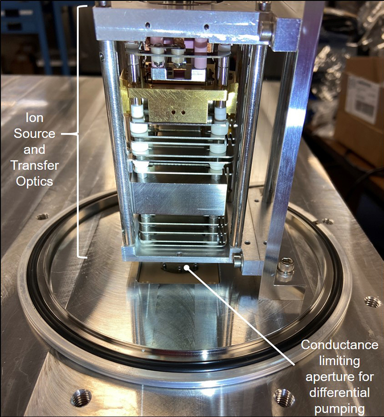
Figure 4: Photograph of the ion source mounted on the aluminum vacuum housing lid.