Background
3DI provides advanced performance beyond traditional ionospheric cold ion instruments (including the competing UT Dallas sensor) in that it performs differential measurements in velocity space, separated by ion composition, and then produces the GDC required measurements, species by species, by integrating appropriately over velocity space. 3DI is well suited for GDC by providing accurate cold ion observations on a fast moving platform: (a) the innovative deflector shape allows fine angular resolutions around the ram direction, (b) the symmetric Electrostatic Analyzer (ESA) provides uniform energy resolution across the FOV, (c) the static mass analysis requires no dead time and allows usage of the high-heritage read-out system, and (d) the sensitivity reduction enables safe operations under occasional high-density cases in GDC altitude.
Fig.1(left) shows a functional diagram of the 3DI Sensor assembly. The top side of the figure points the ram direction of S/C where the ions are flowing in. The 3DI sensor assembly consists of (1) ESA sub-assembly, (2) Lens + Mass Analysis sub-assembly, and (3) Microchannel Plate (MCP) and anode sub-assemblies. Sample ion trajectories are calculated by a numerical modeling for key ion species. All technologies have been demonstrated with a working prototype sensor [Fig.1 (right)] with the SwRI’s Internal Research funding (15-R8725) in a relevant vacuum environment using ion beam. The prototype sensor assembly includes flight-ready read-out electronics and a field-programmable gate arrays (FPGA). Therefore, 3DI is currently at TRL 5. Vibration, shock and thermal tests demonstrated in a relevant GDC environment are needed in the flight package for technical advancement to TRL 6.
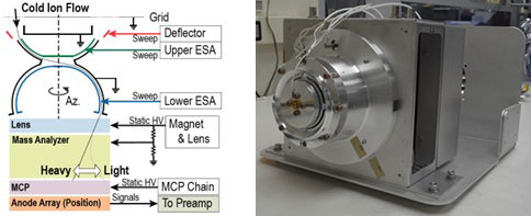
Figure 1: (Left) 3DI Sensor assembly functional diagram. (Right) 3DI prototype developed in the IR project 15-R8725
Approach
The 3DI QETU components are described in Table 1 in detail. Vibration, shock and thermal balance/cycle tests are conducted at SwRI’s thermal vacuum and shock/vibration facilities. QETU consists of (1) flight-identical subassemblies, directly from the prototype, (2) prototype subassemblies redesigned to be flight-identical or flight-like, and (3) the replacement of electronics, that are already at TRL-6 or above, with mass models and heaters to facilitate structural and thermal qualification. Most of the mechanical parts can be directly usable for QETU and all long-lead items (Magnets and MCPs) are available in SwRI. The tasks to be performed in this PDIR will directly address the potential weakness of the 3DI investigation on the selection criteria.
Table 1: Breakdown of the QETU components.
Assembly | Elements | QETU Implementations |
Sensor | Electrostatic and Magnetic Ion Optics | Documented test performance shows agreement with analytical predictions with the prototype sensor. Preliminary environmental analysis completed. Most of the pieces are available from laboratory prototype other than one outer ESA piece. |
Anode Board | The prototype’s micro-pixel anode was Flight-Identical in size and design. The exception is the dimension of the circuit board that has the micro-pixels. The new anode board will be processed using the identical design as the prototype. | |
MCP Holder and MCPs | The holder and MCP design is identical to MMS/HPCA, thus TRL 7 is claimed. The QETU will use 3DI Flight-Identical MCP plates from flight spare detectors of MMS/HPCA. | |
Sensor Housing | A pre-Phase A housing will be fabricated and integrated for QETU with the prototype Sensor Internals, MCP Detector assembly and Ebox. | |
Ebox | Front-End-Electronics | The prototype’s FEE was 3DI flight-like. It is TRL-6 based on heritage use in TRICE 2 and TRACERS For pre- and post-performance testing in-vacuum, the QETU FEE is powered by an external bench supply and will output to an oscilloscope for performance monitoring. |
Sensor Power Supply | The SPS circuits used in 3DI have a heritage of >TRL-6. Mass model and heaters will be used for QETU. | |
Data Processing Unit | The DPU design has a heritage of >TRL-6 from the CYGNSS Command and Data Handling. The FSW, housed in the DPU, is primarily reuse from heritage instruments, running the same processor, such as HIS. Mass model and heaters will be used for QETU. | |
Low Voltage Power Supply | The LVPS design has a heritage of >TRL-6 from the APIS II instrument on the TRICE 2 Rocket. Mass model and heaters will be used for QETU. | |
Electronics Housing | The Structure (individual board trays) used to house the 3DI electronics boards has a heritage of >TRL-6 from the APIS II instrument on the TRICE 2 Rocket. The QETU will use flight-identical board trays with mass models and heaters of the SPS, DPU, and LVPS. This will provide flight identical mass/thermal loading to the Sensor Subassembly during qualification testing to TRL-6. |
Accomplishments
- Mechanical design of structure for vibration testing is complete
- Fabrication of mechanical structure is complete
- Testing of electronics is complete
- Electrical connection and routing to fit into mechanical structure is complete