Background
There are many gas-liquid separation devices used in oil and gas production, gas transmission pipelines, chemical processing, and other industries. Much of the development work for these devices has been supported by tests at low pressure and using simple model fluids, such as air and water to represent real production fluids. There is a strong need to test devices and conduct research at more field-like pressure conditions using field-like fluids, such as natural gas and oils. SwRI has performed these more realistic tests in the Multiphase Flow Facility (MFF) for several years.
SwRI has upgraded its Metering Research Facility (MRF), which has a much greater gas flow capacity than the MFF, to include a wet gas section. SwRI can now provide customers with greater capabilities to test gas-liquid separation and wet gas flow meters, and to perform research on the effects of wet gas flows on pipeline and process industry hardware. The wet gas section within the MFF is shown in Figure 1.

Figure 1: The test section vessel is at the core of the MRF wet gas section.
Approach
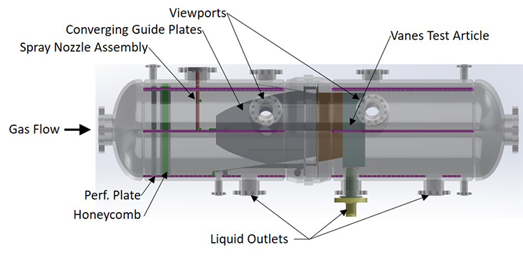
The focus of an SwRI internal research project was to design the unique pressure vessel for this facility improvement. The pressure vessel will be used as the main test section for gas-liquid separation hardware or as the liquid collection vessel for other test hardware placed upstream of the vessel and subjected to wet gas flow conditions. This design was accomplished primarily by the staff of SwRI’s Structural Engineering Department in the Mechanical Engineering Division.
Accomplishments

Figure 2: The test section vessel can be split and separated to give full access for the installation of test articles and flow conditioning hardware.
The pressure vessel has the following features:
- The maximum operating pressure is 1,440 psig at temperatures up to 120°F.
- The vessel was designed in accordance with the ASME Boiler and Pressure Vessel Code, Section VIII.
- The vessel can be separated at its midpoint to allow installation of test articles with a maximum facial dimension of 40 inches transverse to the flow direction. See Figure 2.
- There are multiple ports in the vessel to allow for liquid injection piping, flow visualization windows, liquid extraction from test articles, and instrumentation sensors.
- The vessel has internal brackets to mount equipment for conditioning the flow into or around the test articles.
- The vessel can also serve as the primary separator for other wet gas pipeline test articles that are placed upstream of the vessel.
- The vessel is complete and is now in service at the core of the wet gas section of the MRF as seen in Figure 2. It has been used successfully for tests of vane-type separation devices for the Separation Technology and Research (STAR) Program.

